
Create an account
Log in
Create a new drawing
Name
Drawing type
Drawing scale
Drawing format
Overview of the drawing tool
The drawing
The interface
Navigate in the drawing
Move around the drawing
Zoom in the drawing
Drawing and adding
Draw a line
Curved lines
Draw a rectangle
Draw a dimensioned line
Perpendicular guide
Draw a triangle
Draw a trapezoid
Show dimensions on rectangles, lines, and other shapes
Adding text
Adding symbols
Title block
North arrow
Undo
Move objects
Manipulate objects
The object panel
The object's line style
The object's line color
Line thickness
The object's fill
Copy objects
Import base material
Upload base material
Set the drawing's scale
Choosing the right scale
Remove base material
Export drawing
User Guide #
Drawblueprint is a simple drawing tool that lets you create drawings directly in your web browser. Drawblueprint is online-based, you don't need to download any program to your computer, but instead create all drawings directly in the browser. This also means that all your data is stored on our servers, so you don't need to worry about file management. All changes are also saved automatically.
Drawblueprint takes no responsibility for the accuracy of the documents you create with our tool. We do not issue any guarantee that the drawings will be approved in any process. Our tool is simply a drawing tool. We think it's useful, and hope you will too.
Drawblueprint works on PC and Mac. If you use a smartphone or tablet, the tool will not work as intended. You can create an account, but need to log in on your computer to use the actual drawing tool.
Create an account #
To gain access to Drawblueprint, go to https://app.drawblueprint.com/sign-up and follow the instructions.
Log in #
If you have an account at drawblueprint.com, log in by going to https://app.drawblueprint.com/sign-in and following the instructions.
Enter the email address you used to register the account and press "Send login link".
An email will then be sent to the provided email address. Go to your email inbox and press the link in the message to log in.
If you can't find the email, it may have been sorted as spam. Check your spam folder in your email.
Create a new drawing #
To create a new drawing, press the + New drawing button, at the top of the blue box.
A form will then appear where you enter the drawing's name, scale, and format.
Name #
The name you want to give the drawing.
Drawing type #
Choose whether you want guidance to complete a specific type of drawing.
Drawing scale #
The scale indicates the ratio between the drawing and reality. Common scales are 1:100, 1:400, and 1:500.
At a scale of 1:500, a 1 cm long line on the drawing corresponds to 500 cm in reality. At a scale of 1:100, the same 1 cm line corresponds to 100 cm in reality.
Which scale you should choose depends on what type of document you want to create, and what material you have to work from. Floor plans are often at a scale of 1:100, site plans at a scale of 1:500, and facades and sections at a scale of 1:100. It is common for different construction documents in the same case to have different scales. If you are unsure what to choose, it's a good idea to contact your local building authority.
If you are using base material; check what scale it has, and choose the same. If the base material and the drawing have different scales, the drawing will become incorrect. The base material's scale is indicated as "1:100" somewhere on the material.
Drawing format #
Here you specify the drawing's format. That is, whether it is format "A4", like a regular sheet of paper, or "A3", twice as large as A4. In Drawblueprint you draw directly on a drawing with a specific format. This differs from many CAD programs, where the model is scaleless, and format is set upon export.
If you import drawing material or a map as base material, it needs to be in the same format as the drawing, so that scale and format are not distorted. If you, for example, choose landscape A3 here, then material you later import must also be in landscape A3 format.
Overview of the drawing tool #
The drawing #
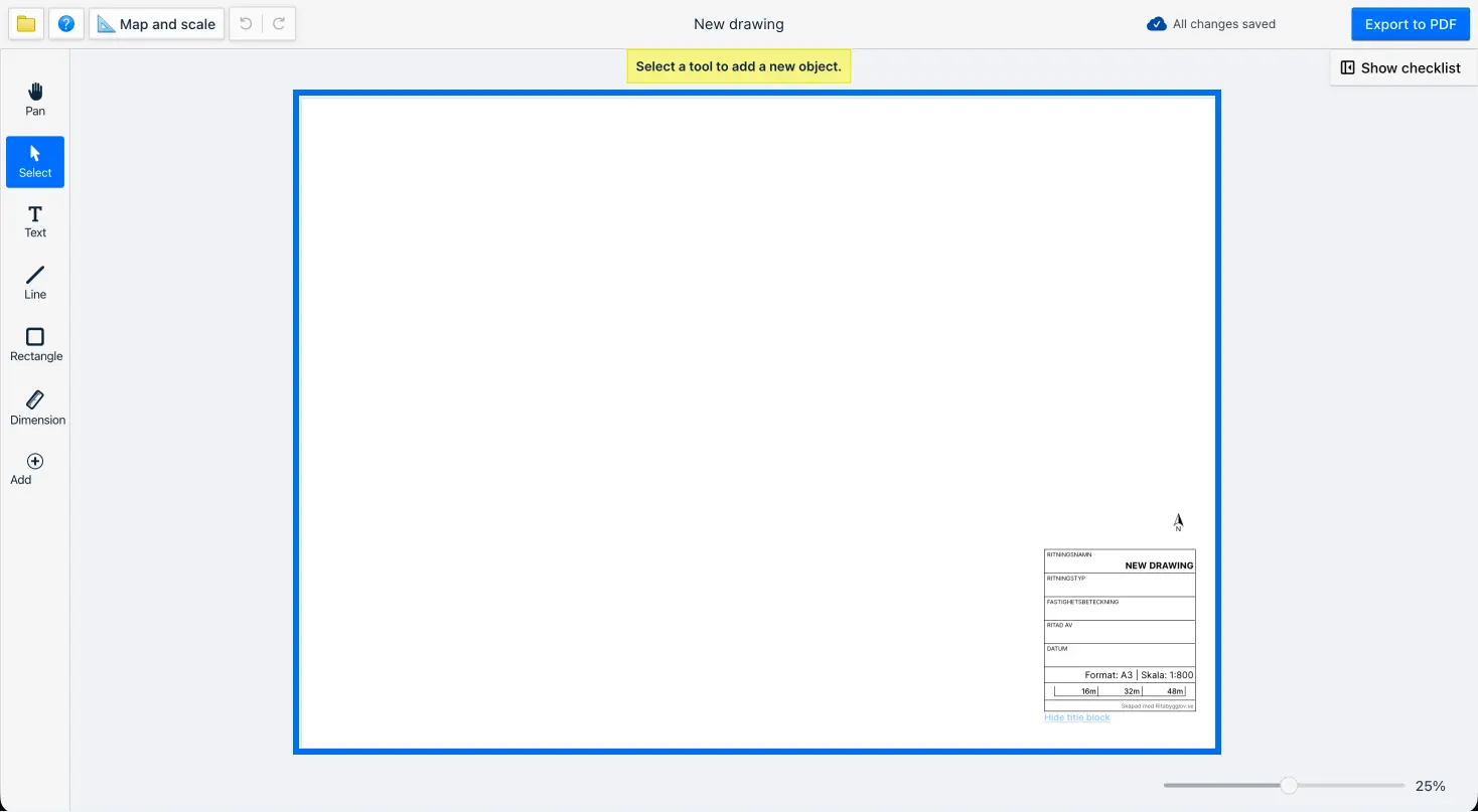
The white box represents the drawing. Like a digital sheet of paper. What you draw on the drawing will be included in the export. What you draw outside of it will not be included in the export.
The interface #
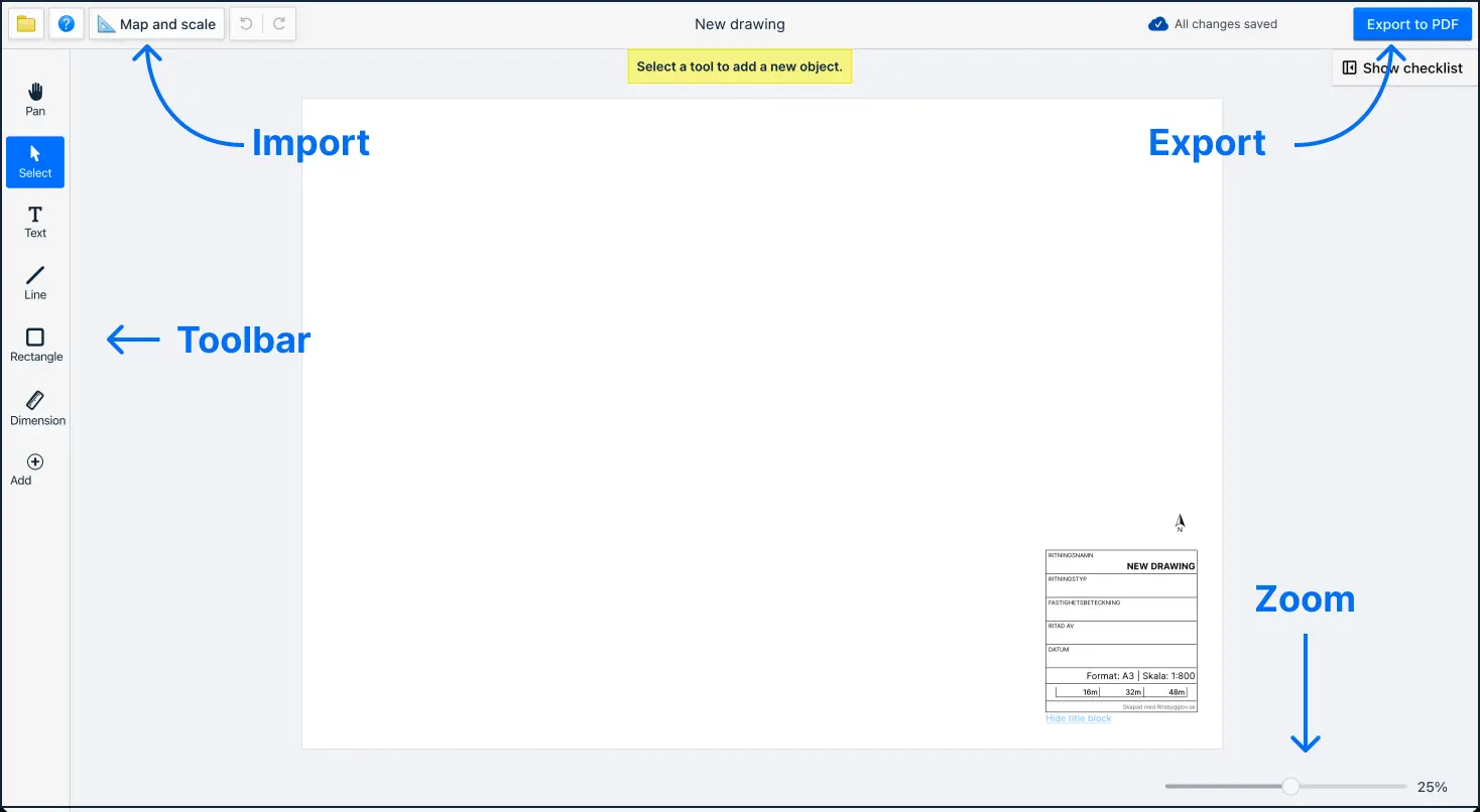
| Button | Function |
|---|---|
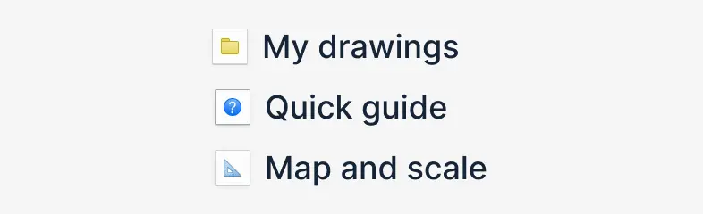
| My drawings | Press here to go back to the overview of all your drawings. |
| Map and scale | Set the drawing's scale. Import map base material. Specify whether the north arrow and title block should be shown on the drawing. |
| Zoom control | Use the buttons here to zoom in and out. |
| Toolbar | Here you choose among the various tools for panning, drawing rectangles, writing text, and drawing lines. |
| Undo | Press to undo the last action or step forward again. |
| Checklist | Step-by-step guide for completing the drawing type you have chosen. |
| Quick guide | Quick guide and link to the user guide. |
| Export button | Press here to export your drawing and download it as a PDF. |
Navigate in the drawing #
Move around the drawing #
To navigate in the drawing, select the hand tool in the toolbar. Click and hold down the mouse pointer, and drag the mouse to navigate.
Or hold down Space while the pointer tool is selected to navigate around the drawing.
If you are using a computer with a trackpad, you can navigate in the drawing by scrolling with the trackpad in different directions.
Zoom in the drawing #
- Drag the zoom slider in the right-hand corner of the screen to zoom in and out of the drawing.
- Press the current zoom value in the bottom right corner, and select a zoom level.
- Hold down ctrl on Windows or cmd on Mac, and scroll with the scroll wheel to zoom.
- Pinch with your fingers on a touchpad to zoom in and out.
Drawing and adding #
Draw a line #
Use the line tool in the tool panel to draw a line on the drawing.
To draw a line, select the line tool and press to place the first point. Continue pressing to place additional points between which the line is drawn. Press Escape or Enter to finish the line.
By holding down the Shift key while drawing, the line locks to angles at 15° intervals or gets assistance placing the next point.
Curved lines #
A line with one or more corners, that is, three or more points, can be curved. This is useful for, for example, drawing a curved driveway, or an arch in a facade drawing.
To curve a line, select the line and move the mouse pointer over the corner you want to round off. A blue handle will then appear at the corner. Press, hold, and drag the handle inward, away from the corner, to round it off. A helper line shows how far the corner can be rounded.
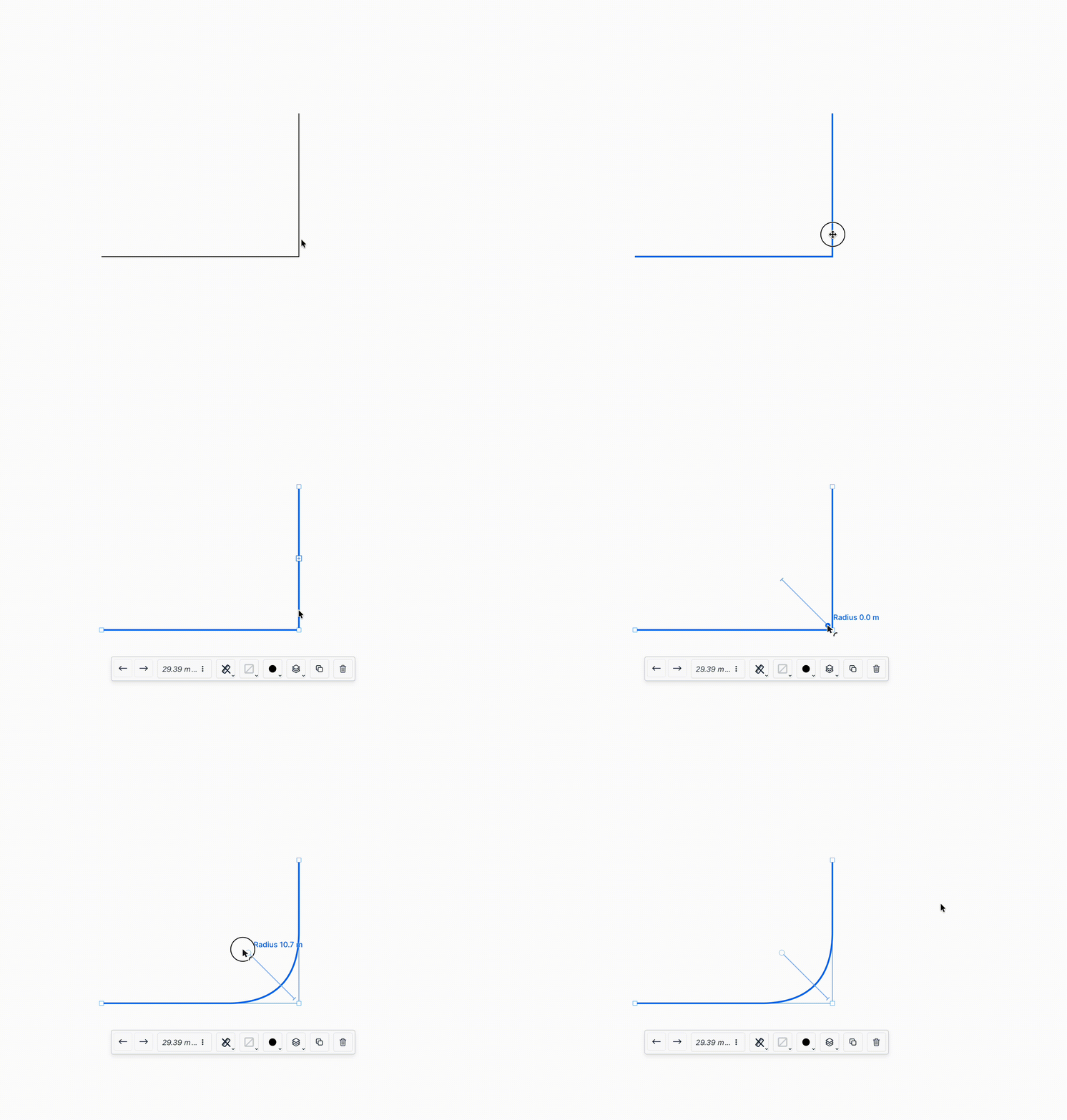
While dragging, the radius in meters is shown next to the handle, so you can see how large the rounding will be in reality.
To make the corner sharp again, drag the handle all the way back to the corner.
Draw a rectangle #
Use the rectangle tool in the tool panel to place a rectangle. You can change the height and width of the rectangle after placing it, as well as rotate it.
To draw a rectangle, select the rectangle tool and press to place the rectangle.
Draw a dimensioned line #
Dimension lines work just like regular lines, but have their length printed on the map. Dimension lines are useful for measuring on the drawing, and for marking out measurements.
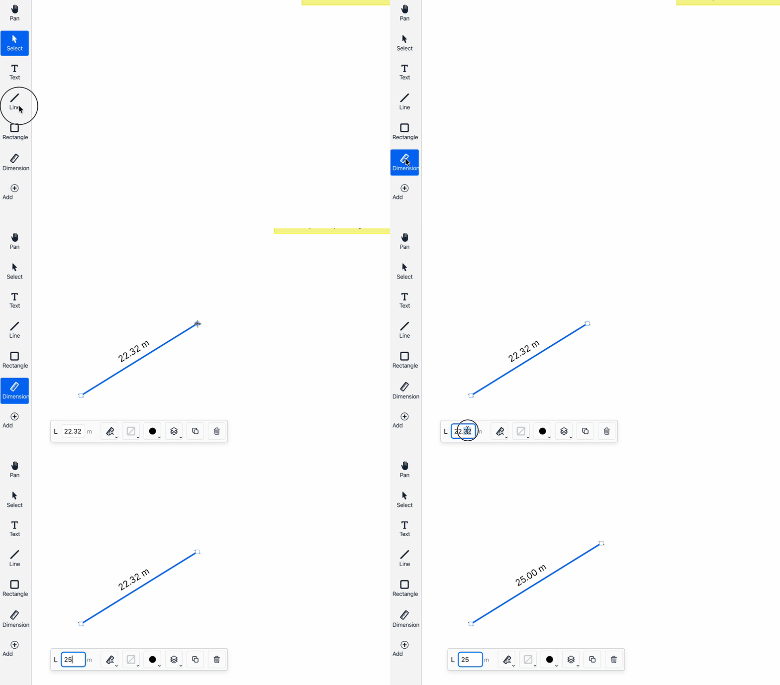
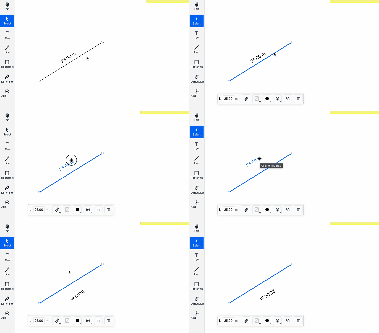
After placing the dimension line, you can press the dimension numbers to make them switch sides. This is useful if the measurements are obscuring something or end up upside down. You can also press, hold, and drag the dimension numbers with the mouse to place them where you want.
Perpendicular guide #
When you draw a dimension line, or select an existing one, the Perpendicular guide button appears below the tool panel. Press the button to turn the guides on, and press it again to turn them off.
When the guides are on, a dashed line is drawn through each of the dimension line's two endpoints, perpendicular to the dimension line. The guides are only shown while the dimension line is being drawn or is selected.
Use the guides to check that you are measuring at a right angle: line the guide up with whatever you are measuring from, a plot border or a facade, for example, and the dimension line is then perpendicular to it. This is often required when showing distances to a plot border in building permit documents.
Draw a triangle #
Use the triangle tool in the tool panel. Press + add and select the triangle to place a triangle. You can change the height and width of the triangle after placing it, as well as rotate it.
To change the triangle's angles you can modify its "apex position". Drag the handle at the top of the triangle, or enter a value in the apex position field. Entering 50% places the apex in the middle and the triangle becomes isosceles. By entering 0% or 100%, the triangle's apex ends up directly above one of the other points; the triangle then becomes a right triangle with a 90° corner.
When the triangle is selected, you can press the Show angles button in the bottom part of the screen to show or hide the triangle's three corner angles in degrees.
Draw a trapezoid #
Use the trapezoid tool in the tool panel. Press + add and select the trapezoid to place a trapezoid. You can change the height and width of the trapezoid after placing it, as well as rotate it.
You can specify the trapezoid's lower and upper height separately in the object panel.
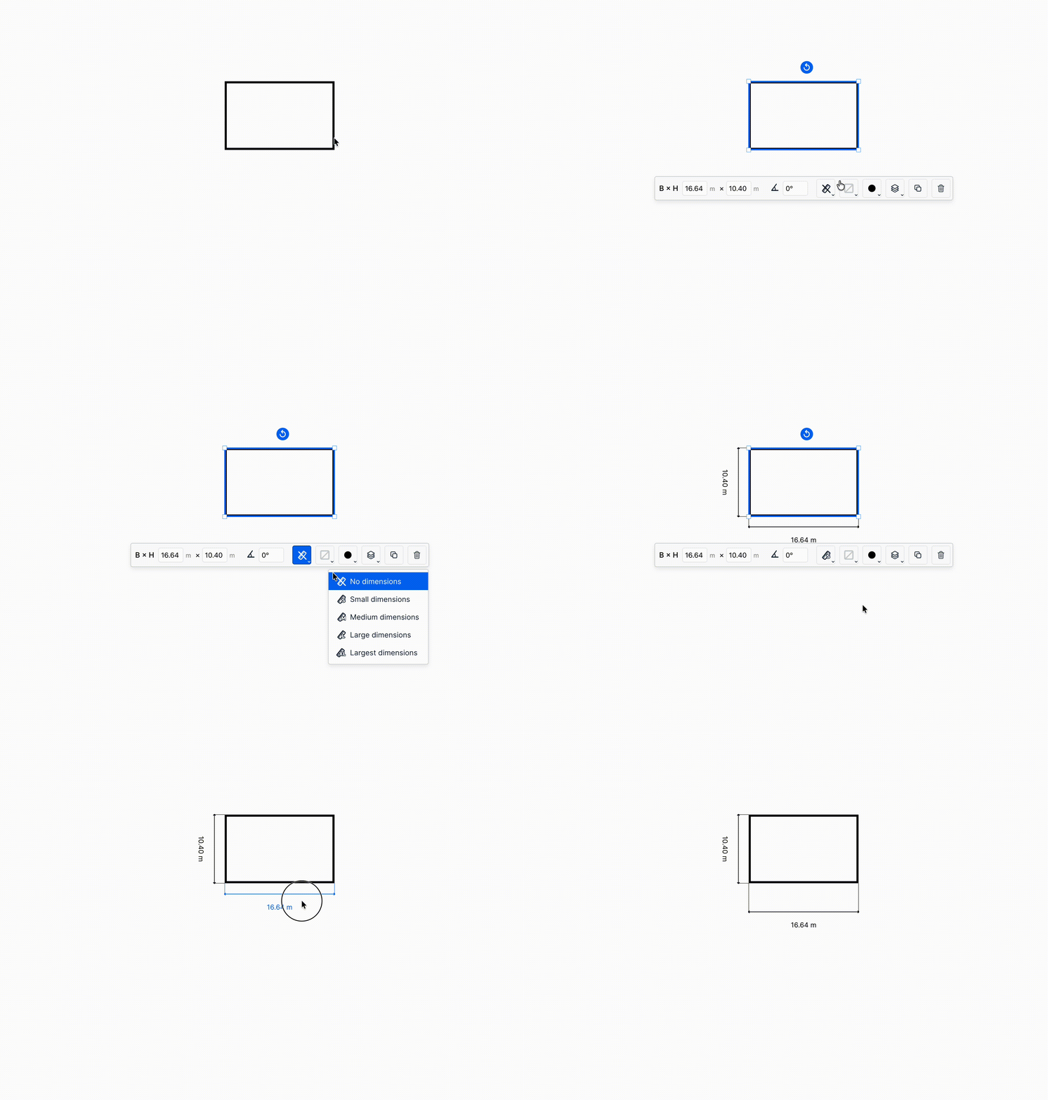
Show dimensions on rectangles, lines, and other shapes #
You can automatically show dimensions for a rectangle, line, or other shapes. Press the element you want to show measurements for, and then press the ruler icon that appears in the object panel. You can press, hold, and drag the measurements to move them.
Adding text #
Add text by selecting the text tool. Then click on the drawing to place the text box.
Texts are moved and rotated just like other elements. Double-click the text to edit it. You can also select the text and then press enter, or press the pencil icon above the selected text box.
Press Escape to finish editing text.
You can change the text's alignment (left, right, or centered), the text size, and its color by selecting the text box and choosing in the control panel.
Adding symbols #
You can place symbols on your drawing. Press add in the tool panel and then select which symbol you want to place. Press with the mouse to place the symbol on the map.
Change the size and shape of a symbol by selecting it and dragging the blue handles, or by entering measurements.
Available symbols include:
- windows in plan and elevation view
- doors in plan and elevation view
- wells
- a symbol for roof pitch - used to indicate the number of degrees the roof slopes
- stairs
Title block #
The title block is the name of the information box found on all drawings. In Drawblueprint you'll find the title block in the bottom right corner.
To fill in information in the title block, click the field you want to write in, and then type directly in the box.
To hide the title block, press the blue text "Hide title block" below the box. To show the title block again, go to Map and scale in the top left corner and check Title block.
North arrow #
The north arrow indicates where north is on a drawing. It is often mandatory on site plans.
In Drawblueprint you'll find the north arrow in the bottom right corner. To set the north arrow in the right direction, use the mouse. Move the mouse over the line, grab the blue handle that then appears, and drag to rotate the arrow.
To hide the north arrow, move the mouse over the north arrow and select "Hide north arrow". To show the north arrow again, go to Map and scale in the top left corner and check North arrow.
Undo #
- Use ctrl + z (or cmd + z on Mac) to undo and step backward. You can also press the undo arrow at the top left.
- Use ctrl + shift + z (or cmd + shift + z on Mac) to step forward again. You can also press the step forward arrow at the top left.
Move objects #
Select an object by clicking on it with the mouse. Press, hold down, and drag to move an object on the drawing.
Press Ctrl + Z to undo.
When you move objects they automatically snap to other objects with red guide lines. Temporarily disable the guide lines by pressing and holding Ctrl (or Cmd on Mac) while you move an object.
Press and hold Shift while moving an object to move it in only one direction, horizontally or vertically on the drawing.
Manipulate objects #
You manipulate existing objects by selecting them and using the object panel that then appears next to the object, or by using the blue handles that appear on selected objects.
| What | How |
|---|---|
| Select | Press an object, for example a line or a rectangle, to select it. When an object is selected, the blue handles appear at the object's ends and the object panel appears below the object. |
| Move | Hold down the mouse pointer on the object and drag with the mouse to move. |
| Resize the object | Press and drag the object's blue handles to change the shape and size of the object. To enter exact measurements, select the numbers in the object panel. |
| Rotate | Press and hold down the rotation handle to rotate an object. You can also enter a degree value in numbers in the object panel. |
The object panel #
The object panel appears next to an object when you select it and lets you manipulate it. Which actions are available depends on which object is selected.
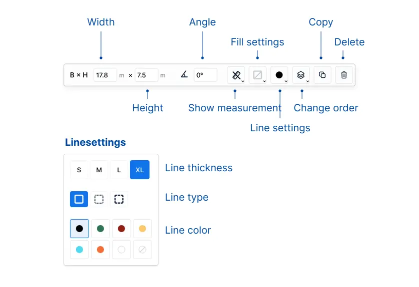
| What | How |
|---|---|
| Arrow end | Press the button to give your selected line an arrow at the end. |
| Set width, height, and angle | Read the object's width, height, and angle. Enter new measurements by typing in the text fields and finishing with Enter. |
| Show measurements | Press the measurement button to show the measurements of the selected object on the drawing. You can then choose whether to show measurements, as well as text size for the measurements. |
| Fill | Choose between no fill, white fill, or a range of patterns. |
| Line settings | Choose line thickness. Choose line style (solid line, dotted, dash-dotted, double, and dashed line.) Choose line color (including transparent). |
| Set text size | Choose between small (S), medium (M), and large (L) text. |
| Change the object's order | Press the layer icon, and choose how you want to change the order. |
| Copy the object | You can also press ctrl + d on Windows, or cmd + d on Mac |
| Delete the object | You can also press Backspace on the keyboard. |
The object's line style #
You can change an object's line style. Select the object and choose the round menu in the object panel.
Choose line style:
- Solid line
- Dotted line
- Dash-dotted line
- Outline
The object's line color #
You can change an object's line color. Select the object and choose the round menu in the object panel.
Choose line color between:
- Black
- Green
- Red
- Yellow
- Turquoise
- Orange
- White
- No line
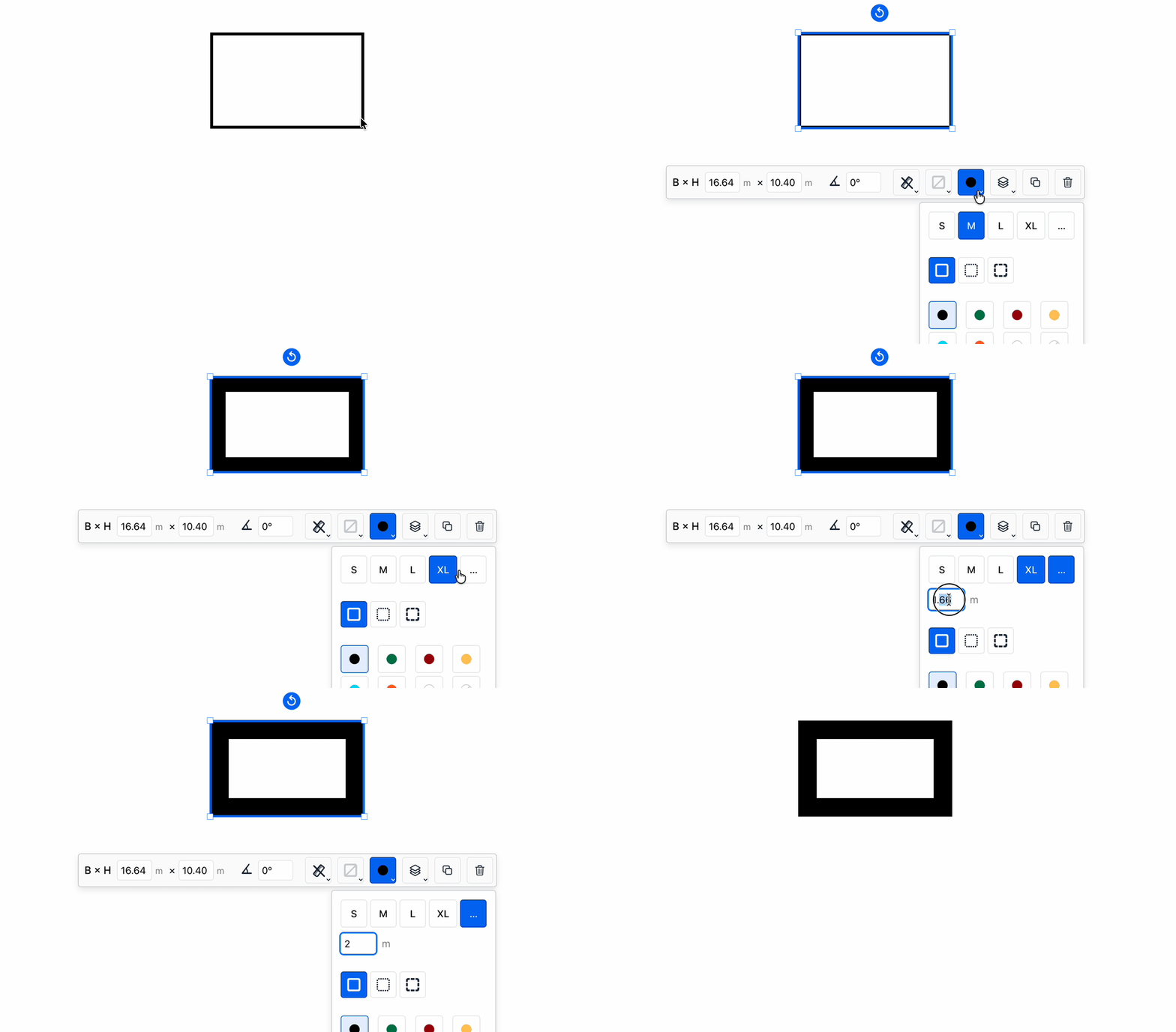
Line thickness #
Change an object's line thickness. Select the object and choose the round menu in the object panel.
Choose a preset line thickness:
- S — Thin line
- M — Medium line
- L — Thick line
- XL — Extra thick line
To specify an exact thickness, press ... next to the thickness options, and enter the exact thickness in meters.
The object's fill #
You can fill objects with color or pattern. Select the object and choose the square menu in the object panel.
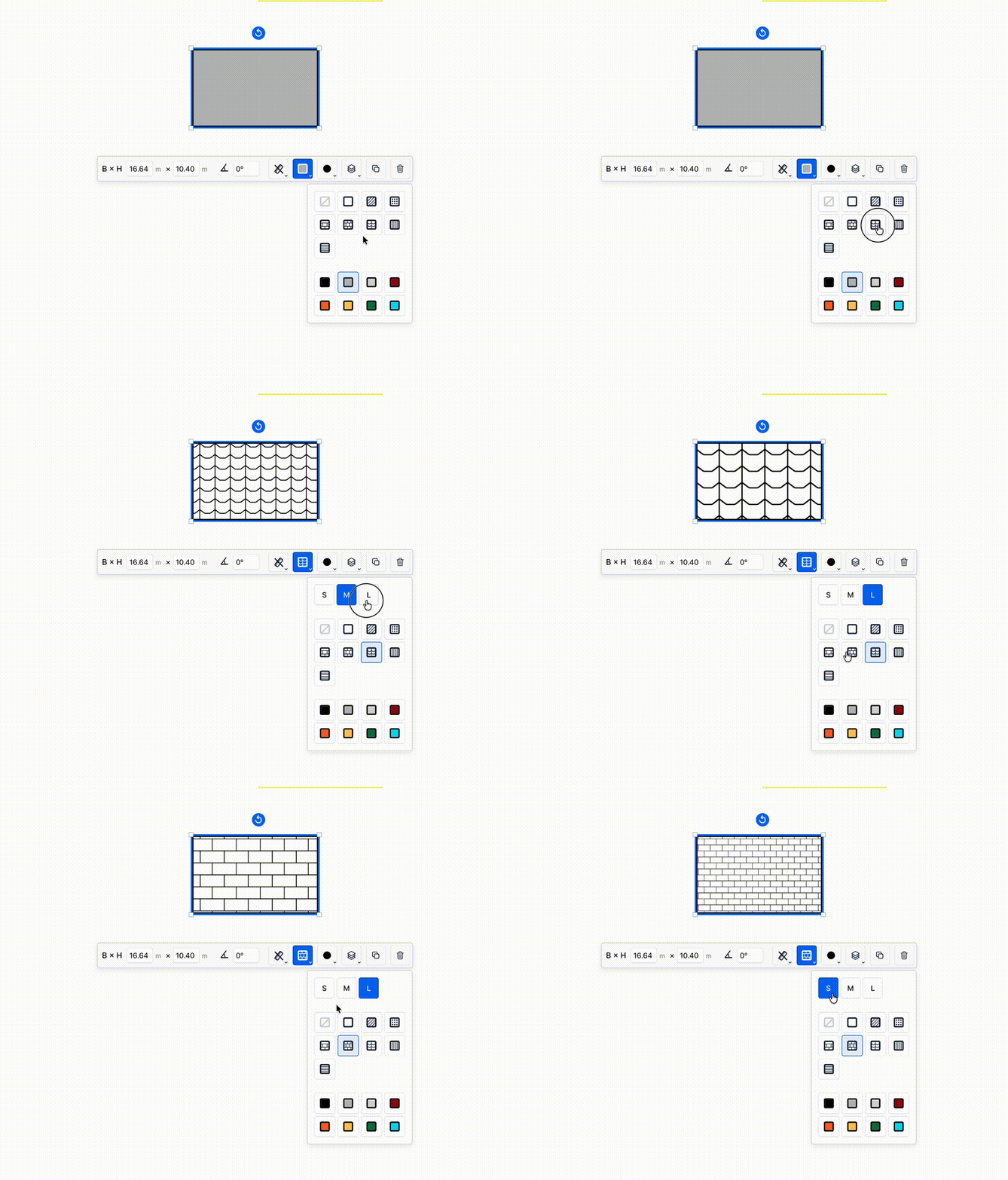
Choose between:
- No pattern
- White fill
- A range of different patterns such as roof tiles, wood panel, dots
- Colored fill
Copy objects #
Use ctrl + C and ctrl + V to copy a selected object. You can also press the duplicate button in the object panel.
Import base material #
In Drawblueprint you can import map base material by uploading a file from your computer.
Upload base material #
Press Map and scale at the top left to import base material.
Then select browse and select the file from your computer. Supported formats are pdf, png, and jpeg.
Accepted file formats are .pdf and .png.
You can upload .pdf files with several pages. You then get to choose which page you want to import into the program.
Make sure the base material's scale and format match your drawing in Drawblueprint
For the import to be to scale, both scale and format need to match the drawing in Drawblueprint. If your drawing in Drawblueprint is set to a scale of 1:400, the material you import must also be at 1:400 for the import to be to scale. Otherwise the measurements will be distorted.
The document's format must also be the same as the drawing in Drawblueprint. If you have chosen A3 landscape in Drawblueprint, the import must also be in A3 landscape format. Drawblueprint supports A3 landscape as well as A3 portrait. Make sure your file import matches this.
Set the drawing's scale #
To set the drawing's scale, click the dropdown menu at the bottom of the box.
Choosing the right scale #
Choose the scale that is right for the drawing's purpose. Ask your local building authority which scale is appropriate.
| Format | Meaning | Common use case |
|---|---|---|
| 1:1000 | 1cm on the drawing corresponds to 1000cm in reality | Overview maps and large areas |
| 1:800 | 1cm on the drawing corresponds to 800cm in reality | Larger site plans |
| 1:500 | 1cm on the drawing corresponds to 500cm in reality | Site plan |
| 1:400 | 1cm on the drawing corresponds to 400cm in reality | Site plan |
| 1:250 | 1cm on the drawing corresponds to 250cm in reality | Smaller site plans |
| 1:200 | 1cm on the drawing corresponds to 200cm in reality | Floor plans and facade drawings |
| 1:100 | 1cm on the drawing corresponds to 100cm in reality | Floor plans and facade drawings |
| 1:50 | 1cm on the drawing corresponds to 50cm in reality | Floor plans and facade drawings |
Remember to set the drawing in Drawblueprint to the same scale as the base material you may want to import.
Remove base material #
To remove base material, go to Map and scale and select Delete.
You must remove already imported material before you can import new material.
Export drawing #
In Drawblueprint you can export your drawing to PDF and download it to your computer. To export the drawing, press the Export to PDF button at the top right. An export of your drawing will then be exported and the download will begin. It may take a few seconds while the drawing is exported before the download starts.
